Data plane
Workload traffic and bandwidth-critical paths.
Host-to-accelerator links, accelerator-to-accelerator fabric assumptions, NIC/DPU paths, storage and boot boundaries.
Public-reference architecture memo
A portfolio-grade system study for an 8-GPU node or rack-slice boundary. It translates board, power, SI/PI, and bring-up experience into platform ownership language without copying any proprietary vendor design.
This dossier demonstrates a target AI/GPU server reasoning boundary. It is not a record of Pengcheng's employer platform, customer deployment, or shipped hyperscale ownership. Verified career experience is listed separately on the Resume page.
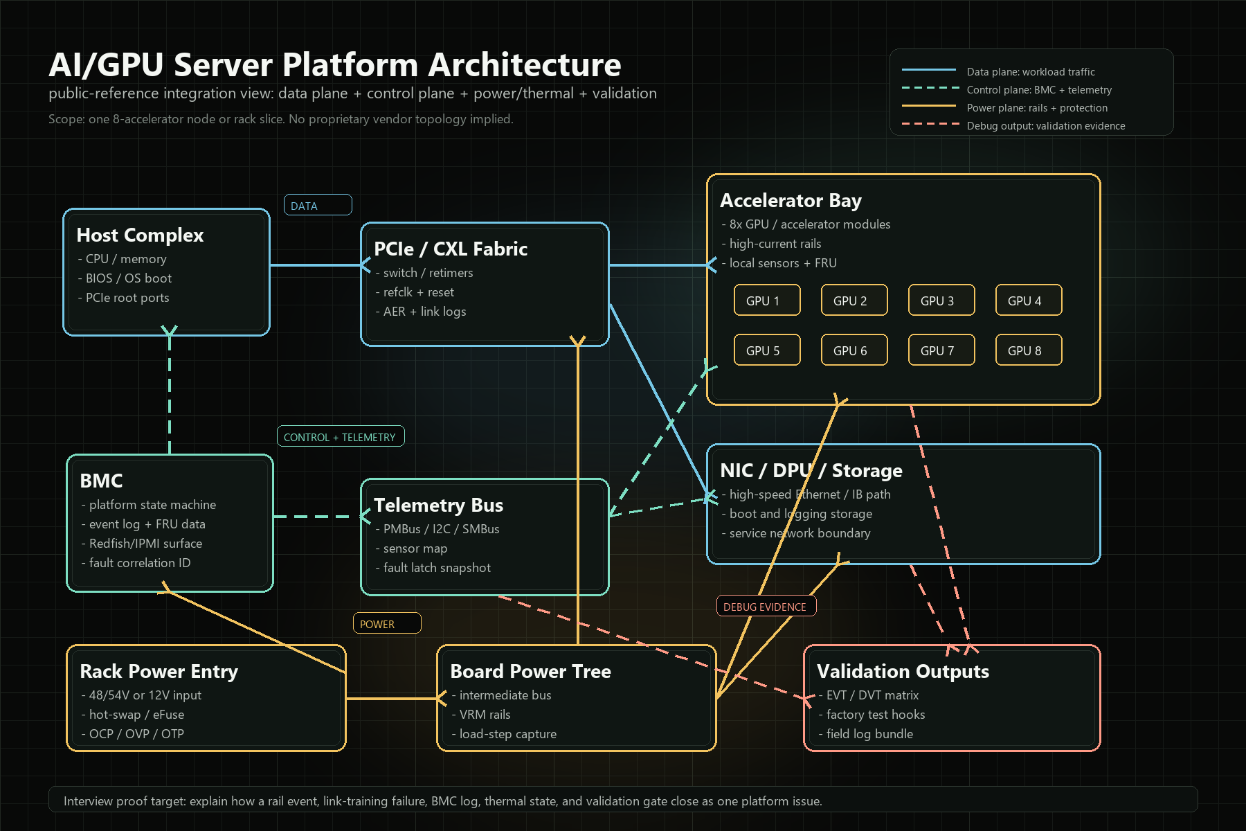
System Architecture
Platform interviews often test whether the candidate can reason across interfaces rather than list components. This map is the narrative spine: what carries workload traffic, what manages the platform, what helps root-cause failures, and what can fail independently.
Data plane
Host-to-accelerator links, accelerator-to-accelerator fabric assumptions, NIC/DPU paths, storage and boot boundaries.
Control plane
BMC ownership, power sequence control, telemetry sampling, firmware handoff, logs, FRU data, field service signals.
Power Delivery
A platform power plan should explain how rails turn on, how faults propagate, how telemetry is sampled, and how a field engineer can distinguish transient droop, protection trip, thermal derating, and firmware policy issues.
Input
48/54V or 12V assumption, power shelf boundary, hot-swap, eFuse, redundancy, surge/inrush, and input telemetry.
Conversion
VRM phase planning, load-step target, SOA, loop stability, bulk/decap strategy, OCP/OVP/OTP policy.
Observation
Voltage/current/temperature samples, fault latches, sampling period, timestamp correlation, and BMC event severity.
SI/PI
| Area | Platform question | Evidence to produce |
|---|---|---|
| Channel budget | Can a link close after board loss, connector loss, cable loss, via transitions, and retimer placement? | Loss budget, retimer decision, equalization assumptions, compliance measurement plan. |
| Reference clock | Could jitter, spread spectrum, clock muxing, or reset timing explain intermittent training? | Clock tree, jitter budget, reset dependency map, oscilloscope capture plan. |
| PI coupling | Can rail noise or PDN impedance convert a power event into a fabric symptom? | PDN target, load transient correlation, rail noise capture during link training. |
| Lab correlation | Does the lab evidence match AER logs, BMC event timeline, and thermal state? | Timestamped bring-up log, BER/compliance data, environmental notes, failure matrix. |
Validation Matrix
| Phase | Exit signal | Failure injection | Factory / field hook |
|---|---|---|---|
| Pre-board | Schematic review, layout constraints, power/SI risk register, test point map. | Review missing rail telemetry, missing reset observability, weak channel margin. | ICT/FCT strategy seeded before layout freeze. |
| Power-up | All rails sequence correctly, PMBus IDs match, fault latches clear, inrush within target. | Inject undervoltage, delayed power-good, sensor missing, fan/pump warning. | Factory rail test and BMC inventory snapshot. |
| Host boot | BIOS/UEFI reaches OS, BMC logs align with host timestamps, FRU data is complete. | Reset timing perturbation, boot device missing, BMC handoff delay. | Golden log bundle for comparison. |
| Fabric bring-up | Expected enumeration, link speed/width, BER/compliance pass, no unexplained AER storm. | Retimer config mismatch, lane reversal error, marginal connector, rail noise stress. | Link-training capture script and RMA triage checklist. |
| Stress / soak | Thermal equilibrium, no derating surprises, stable rails, no recurring correctable errors. | Load step, inlet temp rise, fan/pump fault assumption, workload transition stress. | Field telemetry thresholds and service action policy. |
Debug Closure
Case 01
Retimer, refclk, connector loss, polarity, and rail noise fault tree.
Open caseCase 02
VRM stability, decap, OCP blanking, PMBus sampling, and protection response.
Open caseCase 03
Sensor placement, cold-plate contact, VRM hotspot, derating policy, and validation gate.
Open case